
ワレコ
この所、AVRマイコンやArduinoのプログラミングに挑戦している。
Arduinoを使えば開発作業は楽なのだが、出来ればAVRマイコン単体で使いたい。
その理由は、AVRマイコンならワンチップでこぢんまりとした回路を作れるからだ。
今回はArduinoを使って赤外線リモコンの受信実験をやってみた。
しかしまあ、ワテは気分が乗らないと中々作業が進まない。
この数週間、スランプ気味だった。
何でだろう?
太陽の黒点活動と関係しているのかもしれない。
さて、前回はAVRマイコンを使ってLEDチカチカに成功した。
今回もAVRマイコンで赤外線リモコン受信実験をしたかったのだが、難しそうなのでArduino UNOでやってみた。
結論としては、上手く行った。
では、本題に入ろう。
Arduino UNO互換機で赤外線リモコン受信実験を行う回路作成
Arduino UNO互換機に赤外線リモコン受信モジュールを接続する
下写真が今回の赤外線リモコン受信実験で使用した回路一式だ。
Miuzeiと言う会社のArduino UNO互換機をWindows 10パソコンにUSB接続している。
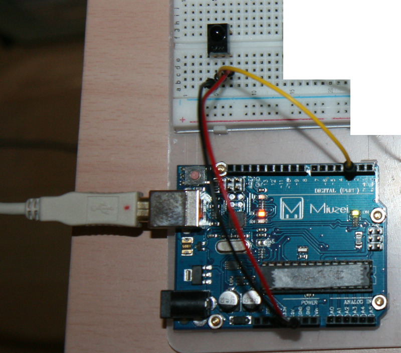
写真 Arduino UNO互換機を使って赤外線リモコン受信実験回路を作成
このMiuzeiのArduino UNO互換キットにはIR Receiverモジュールと言うのが入っているはずなのだが見当たらない。
まあいいわ。
以前、秋月電子で買っていた下写真の赤外線リモコン受信モジュールと言うのが手持ちにあるのでそれを使う事にした。
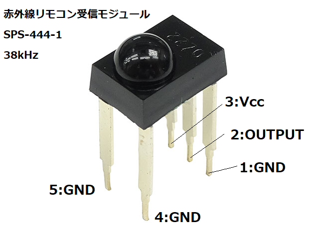
写真 三洋電機 赤外線リモコン受信モジュール SPS-444-1(38kHz)
赤外線リモコン受信モジュール SPS-444-1(38kHz)
[SPS-444-1]
発売日 2005/02/07メーカーカテゴリ 三洋半導体株式会社
テレビ・ビデオ等に使用されている受光モジュールです。足が若干変色しているため、在庫限りの特価販売です、共晶はんだでは全く問題無くはんだ付けできます。砂消しゴム”砂消し”で擦りはんだ付けすれば完璧です、気に無さならければ大変お買い得です。ピンフォトダイオード,アンプ,フイルター回路内蔵。※M-07245のオプトサプライ赤外線リモコンでも使用できます。
※SPS-440-1(I-00614)とは足の長さ(高さ)が違うだけで他は一緒です。
※端子の色が変色していることがあります。■主な仕様
・電源電圧(VCC):5V(4.7~5.3V)
・消費電流(ICC):1.4mA(無信号時.typ)
・副搬送波周波数(fo):38kHz
・受光中心波長(λ):945nm(Δλ=45nm)
・出力レベル:VL=0.5V、VH=4.5V(TTL/C-MOS)
・基板実装面からレンズトップまでの高さ:14.2mm
引用元 https://akizukidenshi.com/catalog/g/gI-00824/
この三洋電機の赤外線リモコン受信モジュール SPS-444-1 を下図のようにArduino UNOと接続した。
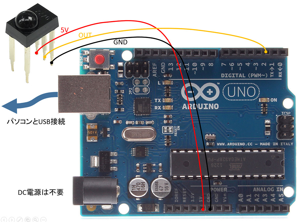
図 Arduino UNOと赤外線リモコン受信モジュールSPS-444-1との接続
赤外線リモコン受信モジュールSPS-444-1は5本足だが、使い方は簡単でVccに5Vを与えれば良い(上図赤色ジャンパー線)。
GNDを黒色ジャンパー線で配線した。
出力端子OutはArduino UNOのDigital PIN 2に接続した(黄色ジャンパー線)。
ジャンパー線三本だけで良いので非常に簡素な回路になる。
AVRマイコンで赤外線リモコン受信実験は失敗
実はArduino UNOを使った実験をする前に、AVRマイコンを単体で使ってこの三洋電機の赤外線リモコン受信モジュールを接続して受信実験をしたのだ。
下写真のブレッドボードの大半がその実験の回路だ。
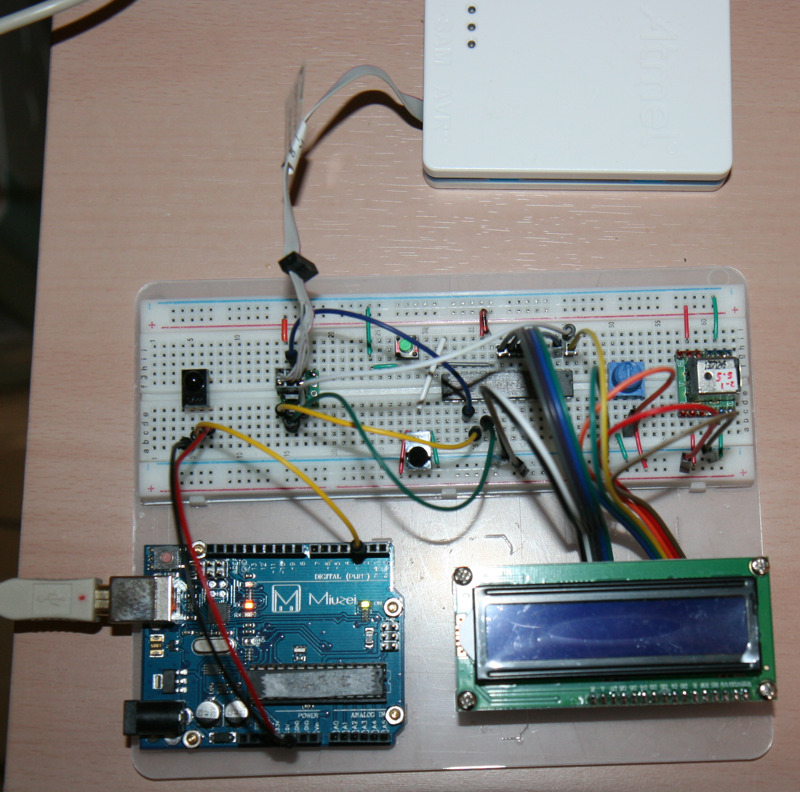
写真 赤外線リモコン受信実験回路が二種類(Arduino UNOとAVRマイコン)
上写真において、左下のArduino UNOが当記事でやっている赤外線リモコン受信実験回路だ。
それ以外の部分はAVRマイコンを使った赤外線リモコン受信実験回路で、白いケースがATMEL-ICEだ。液晶表示にも挑戦したのだが、今のところ、赤外線リモコン受信実験が成功していない。
と言う事で、先ずはArduino UNO版を作って実験したのだ。
Arduino IDEを起動してSimpleReceiverを開く
Arduinoの開発にはArduino IDEと言う無料ソフトを使う。
Windows 10パソコンのデスクトップにArduino IDEのアイコンが追加されているのでそれを起動する。
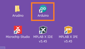
Arduino IDEを起動すると前回終了時の画面が再現されるのでSimpleReceiverサンプルが読み込まれている(下図)。
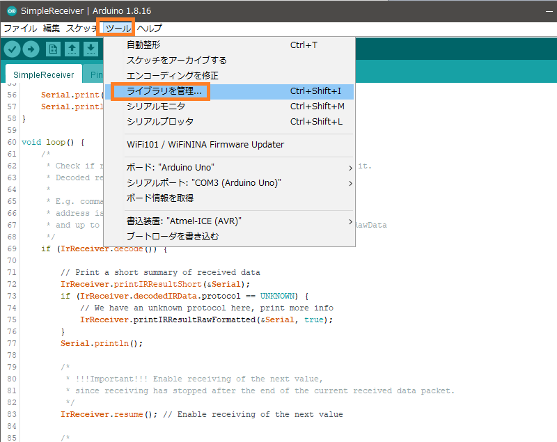
図 Arduino IDEでライブラリを追加する
さて、赤外線リモコン受信実験に使うソースコードはIR remoteと言うサンプルに入っているのだが、そのサンプルをインストールする必要がある。
上図のようにツールー>ライブラリ管理を実行すると下図が出る。
ライブラリマネージャ画面が出るので、検索欄にirremoteと入れると下図のようになる。
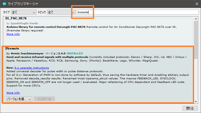
図 ライブラリ検索画面で “irremote” と入れた
ワテの場合は、以前にこの IRremoteライブラリはインストール済なので上図のようにINSTALLEDと表示されている。
無事にIRremoteライブラリのインストールが完了したとしよう。
SimpleReceiverサンプルを読み込んで実行する
ファイルー>スケッチ例ー>IRremoteー>SimpleReceiverを読み込む。
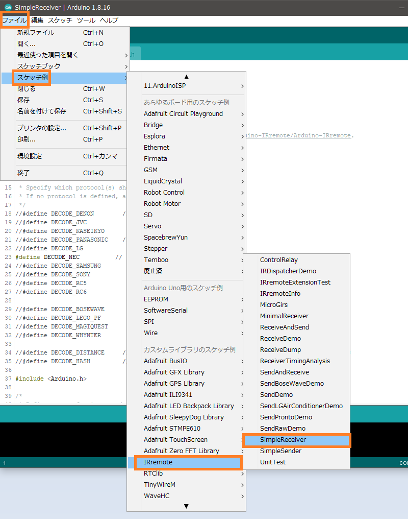
図 SimpleReceiverサンプルを開く
SimpleReceiverサンプルのC++ソースコード
/*
 * SimpleReceiver.cpp
 *
 * Demonstrates receiving NEC IR codes with IRrecv
 *
 *  Copyright (C) 2020-2021  Armin Joachimsmeyer
 *  armin.joachimsmeyer@gmail.com
 *
 *  This file is part of Arduino-IRremote https://github.com/Arduino-IRremote/Arduino-IRremote.
 *
 *  MIT License
 */

/*
 * Specify which protocol(s) should be used for decoding.
 * If no protocol is defined, all protocols are active.
 */
//#define DECODE_DENON        // Includes Sharp
//#define DECODE_JVC
//#define DECODE_KASEIKYO
//#define DECODE_PANASONIC    // the same as DECODE_KASEIKYO
//#define DECODE_LG
#define DECODE_NEC          // Includes Apple and Onkyo
//#define DECODE_SAMSUNG
//#define DECODE_SONY
//#define DECODE_RC5
//#define DECODE_RC6

//#define DECODE_BOSEWAVE
//#define DECODE_LEGO_PF
//#define DECODE_MAGIQUEST
//#define DECODE_WHYNTER

//#define DECODE_DISTANCE     // universal decoder for pulse width or pulse distance protocols
//#define DECODE_HASH         // special decoder for all protocols

#include

/*
 * Define macros for input and output pin etc.
 */
#include "PinDefinitionsAndMore.h"

#include

void setup() {
    Serial.begin(115200);
    // Just to know which program is running on my Arduino
    Serial.println(F("START " __FILE__ " from " __DATE__ "\r\nUsing library version " VERSION_IRREMOTE));

    /*
     * Start the receiver, enable feedback LED and take LED feedback pin from the internal boards definition
     */
    IrReceiver.begin(IR_RECEIVE_PIN, ENABLE_LED_FEEDBACK, USE_DEFAULT_FEEDBACK_LED_PIN);

    Serial.print(F("Ready to receive IR signals at pin "));
    Serial.println(IR_RECEIVE_PIN);
}

void loop() {
    /*
     * Check if received data is available and if yes, try to decode it.
     * Decoded result is in the IrReceiver.decodedIRData structure.
     *
     * E.g. command is in IrReceiver.decodedIRData.command
     * address is in command is in IrReceiver.decodedIRData.address
     * and up to 32 bit raw data in IrReceiver.decodedIRData.decodedRawData
     */
    if (IrReceiver.decode()) {

        // Print a short summary of received data
        IrReceiver.printIRResultShort(&Serial);
        if (IrReceiver.decodedIRData.protocol == UNKNOWN) {
            // We have an unknown protocol here, print more info
            IrReceiver.printIRResultRawFormatted(&Serial, true);
        }
        Serial.println();

        /*
         * !!!Important!!! Enable receiving of the next value,
         * since receiving has stopped after the end of the current received data packet.
         */
        IrReceiver.resume(); // Enable receiving of the next value

        /*
         * Finally, check the received data and perform actions according to the received command
         */
        if (IrReceiver.decodedIRData.command == 0x10) {
            // do something
        } else if (IrReceiver.decodedIRData.command == 0x11) {
            // do something else
        }
    }
}
スケッチをコンパイルしてマイコンボードに書き込む
さっそくSimpleReceiverサンプルをコンパイルしてみる。
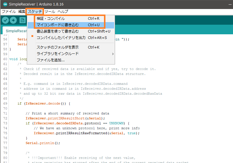
図 SimpleReceiverサンプルをコンパイル成功
エラーも無く無事にコンパイル出来た。
そこで次はマイコンボードに書き込むを実行してみた(下図)。
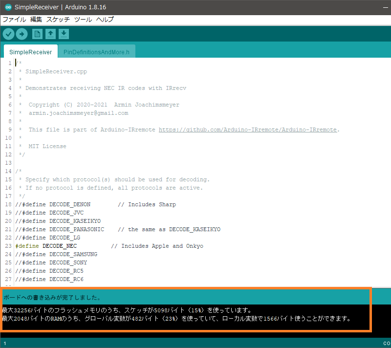
図 SimpleReceiverサンプルをビルドしてマイコンボードに書き込む成功
おお、エエ感じや。
SimpleReceiverサンプルを実行する
いよいよリモコン受信実験開始だ。
シリアルモニタ画面を開く
まずは下図のシリアルモニタアイコンをクリックする。
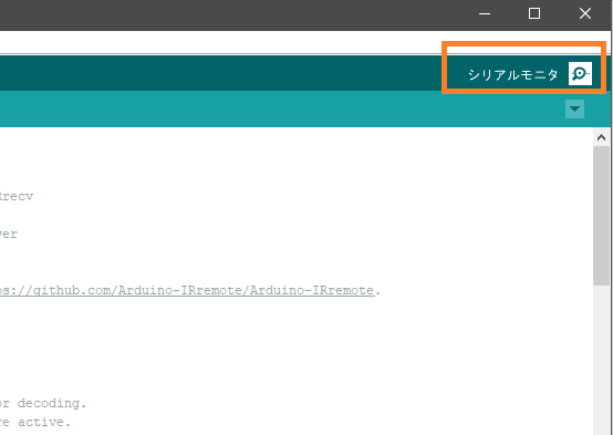
そうすると下図のようにシリアルモニタ画面が開く。
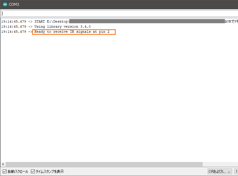
図 シリアルモニタ画面を開いた
ワテのパソコンではシリアル通信にはCOM3ポートが使われている。
ボーレートは先ほどのSimpleReceiverサンプルでsetup()関数内で
 void setup() {
    Serial.begin(115200);
    ...
と定義されている。
そこでCOM3ウインドウ右下にあるボーレートの値設定欄で115,200bpsの値を選択しておいた。
なお、第一章の回路図の説明で、
出力端子OutはArduino UNOのDigital PIN 2に接続した(黄色ジャンパー線)。
と説明したが、Digital PIN 2が赤外線リモコン受信信号の入力ピンになっているのは、
PinDefinitionsAndMore.h
の中で定義されているようなのだが、ワテが使っているArduino UNOでDigital PIN 2が受信用の入力に割り当てられている部分がPinDefinitionsAndMore.hの中のどこなのか良く分からん。
/*
 *  PinDefinitionsAndMore.h
 *
 *  Contains pin definitions for IRremote examples for various platforms
 *  as well as definitions for feedback LED and tone() and includes
 *
 *  Copyright (C) 2021  Armin Joachimsmeyer
 *  armin.joachimsmeyer@gmail.com
 *
 *  This file is part of IRMP https://github.com/Arduino-IRremote/Arduino-IRremote.
 *
 *  Arduino-IRremote is free software: you can redistribute it and/or modify
 *  it under the terms of the GNU General Public License as published by
 *  the Free Software Foundation, either version 3 of the License, or
 *  (at your option) any later version.
 *
 *  This program is distributed in the hope that it will be useful,
 *  but WITHOUT ANY WARRANTY; without even the implied warranty of
 *  MERCHANTABILITY or FITNESS FOR A PARTICULAR PURPOSE.  See the
 *  GNU General Public License for more details.
 *
 *  You should have received a copy of the GNU General Public License
 *  along with this program.  If not, see <http://www.gnu.org/licenses/gpl.html>.
 *
 */

/*
 * Pin mapping table for different platforms
 *
 * Platform     IR input    IR output   Tone
 * -----------------------------------------
 * DEFAULT/AVR  2           3           4
 * ATtinyX5     0           4           3
 * ATtiny167    9           8           5 // Digispark pro number schema
 * ATtiny167    3           2           7
 * ATtiny3217   10          11          3 // TinyCore schema
 * ATtiny1604   2           PA5/3       %
 * SAMD21       3           4           5
 * ESP8266      14 // D5    12 // D6    %
 * ESP32        15          4           %
 * BluePill     PA6         PA7         PA3
 * APOLLO3      11          12          5
 */
//#define IRMP_MEASURE_TIMING // For debugging purposes.
//
#if defined(ESP8266)
#define FEEDBACK_LED_IS_ACTIVE_LOW // The LED on my board is active LOW
#define IR_RECEIVE_PIN          14 // D5
#define IR_RECEIVE_PIN_STRING   "D5"
#define IR_SEND_PIN             12 // D6 - D4/pin 2 is internal LED
#define IR_SEND_PIN_STRING      "D6"
#define tone(a,b,c) void()      // tone() inhibits receive timer
#define noTone(a) void()
#define TONE_PIN                42 // Dummy for examples using it
#define IR_TIMING_TEST_PIN      13 // D7
#define APPLICATION_PIN         0 // D3

#elif defined(ESP32)
#define IR_RECEIVE_PIN          15  // D15
#define IR_SEND_PIN              4  // D4
#define tone(a,b,c) void()      // no tone() available on ESP32
#define noTone(a) void()
#define TONE_PIN                42 // Dummy for examples using it
#define APPLICATION_PIN         16 // RX2 pin

#elif defined(ARDUINO_ARCH_STM32) || defined(ARDUINO_ARCH_STM32F1)
// BluePill in 2 flavors
// Timer 3 of IRMP blocks PA6, PA7, PB0, PB1 for use by Servo or tone()
#define IR_RECEIVE_PIN          PA6
#define IR_RECEIVE_PIN_STRING   "PA6"
#define IR_SEND_PIN             PA7
#define IR_SEND_PIN_STRING      "PA7"
#define TONE_PIN                PA3
#define IR_TIMING_TEST_PIN      PA5
#define APPLICATION_PIN         PA2

#elif defined(__AVR_ATtiny25__) || defined(__AVR_ATtiny45__) || defined(__AVR_ATtiny85__)
#include "ATtinySerialOut.hpp" // Available as Arduino library "ATtinySerialOut". saves 370 bytes program space and 38 bytes RAM for digistump core
#define IR_RECEIVE_PIN  0
#define IR_SEND_PIN     4 // Pin 2 is serial output with ATtinySerialOut. Pin 1 is internal LED and Pin3 is USB+ with pullup on Digispark board.
#define TONE_PIN        3
#define IR_TIMING_TEST_PIN 3

#elif defined(__AVR_ATtiny87__) || defined(__AVR_ATtiny167__)
#include "ATtinySerialOut.hpp" // Available as Arduino library "ATtinySerialOut"
// For ATtiny167 Pins PB6 and PA3 are usable as interrupt source.
#  if defined(ARDUINO_AVR_DIGISPARKPRO)
#define IR_RECEIVE_PIN   9 // PA3 - on Digispark board labeled as pin 9
//#define IR_RECEIVE_PIN  14 // PB6 / INT0 is connected to USB+ on DigisparkPro boards
#define IR_SEND_PIN      8 // PA2 - on Digispark board labeled as pin 8
#define TONE_PIN         5 // PA7
#define IR_TIMING_TEST_PIN 10 // PA4
#  else
#define IR_RECEIVE_PIN  3
#define IR_SEND_PIN     2
#define TONE_PIN        7
#  endif

#elif defined(__AVR_ATtiny88__) // MH-ET Tiny88 board
#include "ATtinySerialOut.hpp" // Available as Arduino library "ATtinySerialOut". Saves 128 bytes program space
// Pin 6 is TX pin 7 is RX
#define IR_RECEIVE_PIN   3 // INT1
#define IR_SEND_PIN      4
#define TONE_PIN         9
#define IR_TIMING_TEST_PIN 8

#elif defined(__AVR_ATtiny3217__)
#define IR_RECEIVE_PIN  10
#define IR_SEND_PIN     11
#define TONE_PIN         3
#define APPLICATION_PIN  5

#elif defined(__AVR_ATtiny1604__)
#define IR_RECEIVE_PIN   2 // To be compatible with interrupt example, pin 2 is chosen here.
#define IR_SEND_PIN      3
#define APPLICATION_PIN  5
#define TONE_PIN        42 // Dummy for examples using it
#define tone(a,b,c) void() // tone() uses the same vector as receive timer
#define noTone(a) void()

#  elif defined(__AVR_ATmega1284__) || defined(__AVR_ATmega1284P__) \
|| defined(__AVR_ATmega644__) || defined(__AVR_ATmega644P__) \
|| defined(__AVR_ATmega324P__) || defined(__AVR_ATmega324A__) \
|| defined(__AVR_ATmega324PA__) || defined(__AVR_ATmega164A__) \
|| defined(__AVR_ATmega164P__) || defined(__AVR_ATmega32__) \
|| defined(__AVR_ATmega16__) || defined(__AVR_ATmega8535__) \
|| defined(__AVR_ATmega64__) || defined(__AVR_ATmega128__) \
|| defined(__AVR_ATmega1281__) || defined(__AVR_ATmega2561__) \
|| defined(__AVR_ATmega8515__) || defined(__AVR_ATmega162__)
#define IR_RECEIVE_PIN      2
#define IR_SEND_PIN        13
#define TONE_PIN            4
#define APPLICATION_PIN     5
#define ALTERNATIVE_IR_FEEDBACK_LED_PIN 6 // E.g. used for examples which use LED_BUILDIN for example output.
#define IR_TIMING_TEST_PIN  7

#elif defined(ARDUINO_ARCH_APOLLO3)
#define IR_RECEIVE_PIN  11
#define IR_SEND_PIN     12
#define TONE_PIN         5

#elif defined(ARDUINO_ARCH_MBED) // Arduino Nano 33 BLE
#define IR_RECEIVE_PIN      2
#define IR_SEND_PIN         3
#define TONE_PIN            4
#define APPLICATION_PIN     5
#define ALTERNATIVE_IR_FEEDBACK_LED_PIN 6 // E.g. used for examples which use LED_BUILDIN for example output.
#define IR_TIMING_TEST_PIN  7

#elif defined(TEENSYDUINO)
#define IR_RECEIVE_PIN      2
#define IR_SEND_PIN         3
#define TONE_PIN            4
#define APPLICATION_PIN     5
#define ALTERNATIVE_IR_FEEDBACK_LED_PIN 6 // E.g. used for examples which use LED_BUILDIN for example output.
#define IR_TIMING_TEST_PIN  7

#elif defined(__AVR__)
#define IR_RECEIVE_PIN      2 // To be compatible with interrupt example, pin 2 is chosen here.
#define IR_SEND_PIN         3
#define TONE_PIN            4
#define APPLICATION_PIN     5
#define ALTERNATIVE_IR_FEEDBACK_LED_PIN 6 // E.g. used for examples which use LED_BUILDIN for example output.
#define IR_TIMING_TEST_PIN  7

#elif defined(ARDUINO_ARCH_SAMD) || defined(ARDUINO_ARCH_SAM)
#define IR_RECEIVE_PIN      2
#define IR_SEND_PIN         3
#define TONE_PIN            4
#define APPLICATION_PIN     5
#define ALTERNATIVE_IR_FEEDBACK_LED_PIN 6 // E.g. used for examples which use LED_BUILDIN for example output.
#define IR_TIMING_TEST_PIN  7

// On the Zero and others we switch explicitly to SerialUSB
#define Serial SerialUSB

// Definitions for the Chinese SAMD21 M0-Mini clone, which has no led connected to D13/PA17.
// Attention!!! D2 and D4 are switched on these boards!!!
// If you connect the LED, it is on pin 24/PB11. In this case activate the next two lines.
//#undef LED_BUILTIN
//#define LED_BUILTIN 24 // PB11
// As an alternative you can choose pin 25, it is the RX-LED pin (PB03), but active low.In this case activate the next 3 lines.
//#undef LED_BUILTIN
//#define LED_BUILTIN 25 // PB03
//#define FEEDBACK_LED_IS_ACTIVE_LOW // The RX LED on the M0-Mini is active LOW

#else
#warning Board / CPU is not detected using pre-processor symbols -> using default values, which may not fit. Please extend PinDefinitionsAndMore.h.
// Default valued for unidentified boards
#define IR_RECEIVE_PIN      2
#define IR_SEND_PIN         3
#define TONE_PIN            4
#define APPLICATION_PIN     5
#define ALTERNATIVE_IR_FEEDBACK_LED_PIN 6 // E.g. used for examples which use LED_BUILDIN for example output.
#define IR_TIMING_TEST_PIN  7
#endif // defined(ESP8266)

#if !defined (FLASHEND)
#define FLASHEND 0xFFFF // Dummy value for platforms where FLASHEND is not defined
#endif
/*
 * Helper macro for getting a macro definition as string
 */
#define STR_HELPER(x) #x
#define STR(x) STR_HELPER(x)
コード PinDefinitionsAndMore.h
でも、COM3ウインドウで
と表示されているので、Digital PIN 2が赤外線リモコン受信信号の入力ピンになっているのは確かだ。
秋月リモコンのスイッチを押してみる
さて、下写真の秋月電子で買っていたリモコンを押してみる。
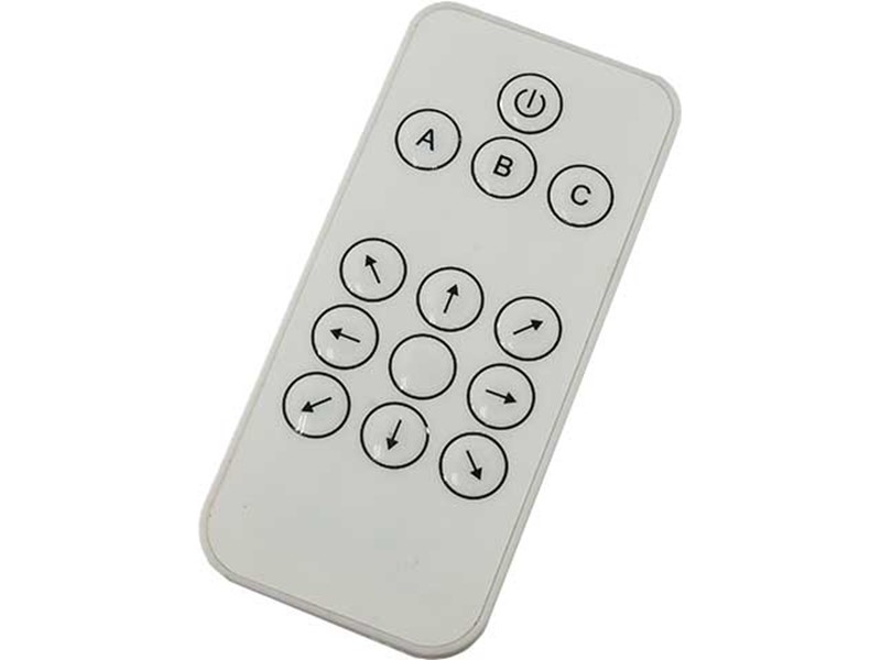
写真 秋月電子で買っていたリモコン
オプトサプライ赤外線リモコン
[OE13KIR]
発売日 2014/06/03メーカーカテゴリ OptoSupply
■特長
・赤外線を使用したリモコンです:波長940nm
・キー数:13(8方向キー+5機能キー)
・キャリア周波数:38KHz 弊社販売の赤外線リモコン受光モジュール(I-00872、I-00824、I-00573)等に対応します。
・CR2025電池(3Vコイン型リチウム電池)使用で薄型です。
・サイズ:幅40.5x長さ86.5x厚さ7.5mm
・重量:約17グラム(電池を含む)
・出力信号形式は「NECフォーマット」準拠です。
引用元 https://akizukidenshi.com/catalog/g/gM-07245/
赤外線リモコン信号を受信出来たぞ
その結果、下図オレンジ色枠に示すように何や知らんが受信に成功したようだ。
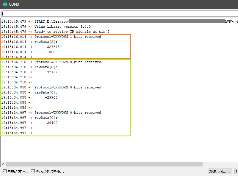
図 秋月電子リモコン(オレンジ色)と日立LED天井照明のリモコン(黄緑色)の受信データ
次に、ワテの居室天井にある日立LED照明のリモコンボタン「おこのみ」を押したら、黄緑色枠で示す十数行の受信結果が表示された。
素晴らしい。
ワテもやれば出来るがな。
まとめ

ワレコ
Arduino、AVR、PIC、Raspberry PIなど色んなワンチップマイコンがある。
ワテの場合は、マイコン初心者なので取り敢えずArduinoから始めて、次はAVRマイコンに挑戦する予定だ。
当記事ではArduino UNOと秋月電子で買っていた赤外線リモコン受信モジュールを使って、38kHz赤外線リモコン信号の受信実験の手順を紹介した。
Arduino初心者のワテであるが、自称プログラミングの世界的達人なので、プログラミングに関しては不安は無い。
しかしながらブレッドボードに多数のジャンパー線で試作回路を組み上げるのは、あまり好きでは無いのだ。面倒なので。
でも今回の実験ではArduino UNOと赤外線受信モジュールとは三本のジャンパー線で接続するだけなので、三十分も掛からずに実験に成功した。
一方、実はその前にAVRマイコン単体と赤外線受信モジュールを使ってブレッドボードに組んだ受信回路をATMEL-ICEとMicrochip Studioで制御する実験をしたのだが、残念ながらうまく行かなかった。
具体的には、ネット検索して見付けた回路はATmega16/ATmega32を使っている回路なのだが、ワテの場合はATmega328Pを使っているので、ネットで見付けたソースコードはデバイスをATmga328Pに変えただけではビルドが成功しなかったのだ。
なので、今後はその辺りを調査して、AVRマイコン単体で使って秋月電子で買っていたリモコン受信モジュールの組み合わせで、赤外線リモコン受信実験を成功させたいと思っている。
Arduinoを学ぶ
(続く)

![ELEGOO Arduino用UNO R3スターターキット レベルアップ チュートリアル付 mega2560 r3 nanoと互換 [並行輸入品]](https://m.media-amazon.com/images/I/51m+CZP2l3L._SL160_.jpg)






コメント